
Sand Casting
Overview
Process Introduction
Process Animation
Equipment
Materials
Capabilities
3D Printing Technology
Typical Products
Overview
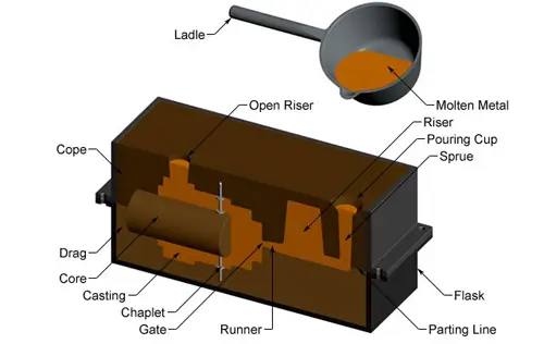
Sand casting, the most widely used casting process, utilizes expendable sand molds to form complex metal parts that can be made from almost any alloy. Because the sand mold must be broken to remove the part called a casting, productivity in sand casting is often low. The sand casting process involves the use of furnaces, metals, patterns and sand molds. The metal is melted in a furnace and then poured with a ladle into the cavity of the sand mold, which is formed from the pattern. The sand mold is separated along the parting line, and the solidified casting can be taken out. The next section describes the steps in this process in more detail.
Sand casting is used to produce a wide variety of metal components with complex geometries. These parts can vary greatly in size and weight, ranging from a couple ounces to several tons. Some smaller sand cast parts include components as gears, pulleys, crankshafts, connecting rods, and propellers. Larger applications include housings for large equipment and heavy machine bases. Sand casting is also common in producing automobile components, such as engine blocks, engine manifolds, cylinder heads, and transmission cases.
Process Introduction
-
Mold Making – The first step in the sand casting process is to make the casting mold. In a one-shot mold process, this step must be performed for each casting. Sand molds are formed by filling each half of the mold with sand. Sand is filled around the model, which is a replica of the external shape of the casting. When the pattern is removed, the cavity that will form the casting remains. Any internal features of the casting that cannot be formed by the mold are formed from individual cores, which are made from sand before the mold is formed. More details on mold making are covered in the next section. Mold making time includes positioning the model, sanding and removing the model. Molding time is affected by part size, core count and sand mold type. If the mold type requires heating or baking time, the mold making time will increase greatly. Additionally, a lubricant is often applied to the cavity surfaces to facilitate removal of the casting. The use of lubricants also improves the fluidity of the metal and can improve the surface finish of castings. The lubricant used is selected according to the temperature of the sand and molten metal.
-
Clamping – Once the mold has been made, it must be prepared for pouring molten metal. Lubricate the cavity surfaces first to facilitate removal of the casting. Then, the core is positioned and the mold halves are closed and clamped securely together. It is critical that the mold halves remain firmly closed to prevent any loss of material.
-
Pouring – Molten metal is kept at a set temperature in a furnace. Once the mold is closed, the molten metal can be poured from the holding vessel in the furnace and poured into the mold. Pouring can be done manually or by automated machines. Enough molten metal must be poured to fill the entire cavity and all channels in the mold. Fill times are very short to prevent premature solidification of any part of the metal.
-
Cooling – The molten metal poured into the mold begins to cool and solidify once it enters the cavity. When the entire cavity is filled and the molten metal solidifies, the final shape of the casting is formed. The mold can only be opened after the cooling time has elapsed. The required cooling time can be estimated based on the wall thickness of the casting and the temperature of the metal. Most possible defects are the result of the solidification process. If some molten metal cools too quickly, parts may develop shrinkage, cracks, or incomplete sections. Precautions can be taken when designing parts and molds and will be explored in later chapters.
-
Removal – After a predetermined set time has elapsed, the sand mold can simply be broken and the casting removed. This step is sometimes called shakeout and is usually performed by a vibrating machine that vibrates the sand and casts it from the flask. Once removed, the surface of the casting may have some sand and oxide adhered to it. Shot peening is sometimes used to remove any remaining grit, especially on interior surfaces, and to reduce surface roughness.
- Dressing – During cooling, material from the channels of the mold solidifies and adheres to the part. This excess material must be trimmed from the casting by cutting or sawing or using a trimming machine. The time required to trim excess material can be estimated based on the dimensions of the casting shell. Larger castings require longer dressing times. The waste material from this trimming is either discarded or reused in the sand casting process. However, scrap may need to be reconditioned to the proper chemical composition before being combined with non-recycled metals and reused.
Process Animation
Equipment
Mold
In sand casting, the main piece of equipment is the mold, which consists of several components. The mold is divided into two halves – the top half (top half) and the bottom half (bottom half), which meet along the parting line. Both mold halves are contained within a box called a flask, which itself is divided along this parting line. The mold cavity is formed by filling sand around the pattern in each half of the sandbox. Sand can be baled by hand, but machines that use pressure or impact ensure even baling of the sand and require far less time, increasing productivity. Once the sand is filled and the pattern is removed, a cavity is left that forms the outer shape of the casting. Some of the interior surfaces of the casting may be formed by cores.
Cores are additional components that form the internal holes and channels of a casting. Cores are usually made of sand so they can be shaken out of the casting, rather than requiring the necessary geometry to slide out. Thus, sand cores allow the fabrication of many complex internal features. Each core is positioned in the mold prior to pouring the molten metal. To hold each core in place, the pattern has grooves called core prints that hold the core in place. However, the core may still move due to the buoyancy of the molten metal. Forks provide further support to the kernel. These are small metal pieces that are held between the core and cavity surface. The ringlet must be made of a metal that melts at a higher temperature than the metal being cast in order to maintain its structure. After solidification, the colums will be poured inside the casting and excess material protruding from the colums must be removed.
In addition to the exterior and interior features of the casting, other features must be incorporated into the mold to accommodate the flow of molten metal. The molten metal is poured into the pouring basin, which is a large depression in the top of the sand mold. Molten metal leaks from the bottom of this basin and flows down main channels, called sprues. The gate is then connected to a series of channels called runners that carry the molten metal into the cavity. At the end of each runner, molten metal enters the cavity through gates that control the flow rate and minimize turbulence. Usually connected to the runner system is the riser. Risers are chambers filled with molten metal that provide an additional source of metal during solidification. As the casting cools, the molten metal shrinks, requiring additional material. A similar feature that helps reduce shrinkage is the open riser. Allows the first material to enter the cavity to pass through completely and into the open riser. This strategy prevents premature solidification of molten metal and provides a source of material to compensate for shrinkage. Finally, small passages from the cavity to the outside of the mold are also included. These channels act as vents to allow gas to escape from the cavity. The porosity of the sand also allows air to escape, but additional ventilation holes are sometimes required. Molten metal flowing through all channels (sprue, runners and risers) solidifies and adheres to the casting and must be separated from the part after removal.

Sand Mold-Opened
Sand Mold-Closed
Sand
The sand used to make the mold is usually silica sand (SiO2), which is mixed with a binder to help maintain the shape of the mold cavity. Using sand as a mold material brings many benefits to the foundry process. Sand is very cheap and resistant to high temperatures, making it possible to cast many metals with high melting temperatures. Mold sand is prepared differently, with the following four unique types of sand molds.
-
Green Sand Molds – Green sand molds use a mixture of sand, water, and clay or binder. A typical composition of the mix is 90% sand, 3% water and 7% clay or binder. Green sand molds are the cheapest and most widely available.
-
Dry-skin molds – Dry-skin molds start out like greensand molds, but with the addition of an additional binder material and the cavity surface is dried by torches or heat lamps to increase mold strength. Doing so also improves dimensional accuracy and surface finish at the expense of collapsibility. Dry skin molds are more expensive and require more time, thus reducing productivity.
-
Dry Sand Molds – In dry sand molds (sometimes called cold box molds), sand is mixed with an organic binder only. Strengthen the mold by baking in the oven. The resulting mold has high dimensional accuracy, but is expensive and has low productivity.
-
No-bake molds – In no-bake molds, sand is mixed with liquid resin and hardened at room temperature.
The quality of the sand used also greatly affects the quality of the casting, which is usually described by the following five measures:
-
Strength – The ability of the sand to hold its shape.
-
Permeability – the ability to allow entrapped gases to escape through the sand. Higher permeability can reduce mold porosity, but lower permeability can produce better surface finish. Permeability is determined by the size and shape of the sand grains.
-
Thermal Stability – The ability to resist damage, such as cracking, from the heat of molten metal.
-
Collapsibility – The ability of the sand to collapse or more precisely compress during the solidification of the casting. If the sand cannot compress, the casting will not be able to shrink freely in the mold and cause cracking.
- Reusability – the ability of the sand to be reused for future sand molds.
Packing Equipment
There are many ways to load sand into molds. As mentioned above, the sand can be hand loaded into the mold. However, there are several types of equipment that can fill sand more effectively and efficiently. One such machine is called a sand blaster, which fills a flask with sand by pushing it under high pressure. A vibrating squeezer is a common piece of equipment that quickly vibrates the sand box to distribute the sand, which is then compacted in the sand box using hydraulic pressure. Another method, called impact molding, uses controlled explosions to drive and compact the sand into the flask. In a method that can be thought of as the opposite, vacuum forming fills the sand with sand by removing the air between the sand box and the thin plastic sheet that covers the model.
The packaging of the sand is also automated in a process known as boxless molding. Despite the process name, flask is still used. In traditional sand casting, a new flask is used for each mold. Flaskless molding, however, uses a single master flask in the automated process of creating sand molds. The flasks move along the conveyor belt and blow the sand according to the internal pattern. This automated process greatly increases productivity and has many benefits for castings as well. Boxless molding produces uniform, high-density molds for excellent casting quality. Additionally, the automated process results in very little variation between castings.
Materials
Sand casting can use almost any alloy. One advantage of sand casting is the ability to cast materials with high melting temperatures, including steel, nickel and titanium. The four most common materials used in sand casting and their melting temperatures are shown below.
Materials
Melting temperature
Aluminum alloys
1220 °F (660 °C)
Brass alloys
1980 °F (1082 °C)
Cast iron
1990-2300 °F (1088-1260 °C)
Cast steel
2500 °F (1371 °C)
Capabilities
Region
Process
Weight (kg)
Process Parameter
Suitability
Mexico
Sinto FBO Automatic Green Sand Molding Line
KW Automatic Green Sand Molding Line
0.5-40
30-400
Flask size:
610×508×250/250 mm
100 molds per hour
Flask size:
1350×1000×450/450 ~250/250mm
100 molds per hour
Elbow, cover, bracket, manifold, bearing housing, transmission parts, impeller, turbine casing, and more
Housing, case, cover, wheel, carrier, bracket, flywheel, flywheel housing, gear housing, cylinder block, cylinder head, oil pan, shaft, and more
China
Sinto FBO Automatic Green Sand Molding Line
IMF Automatic
Resin Sand Molding
Line
IMF Automatic
Resin Sand Molding
Line
Resin Sand
Molding, Pit Pouring
0.5-40
20~220
30-600
10-8000
Flask size:
610×508×250/250 mm
80 molds per hour
Flask size:
1200x800x500/500mm;
15 molds/hour
Flask size:
1600×1200×600/600mm;
10 molds per hour
Flask size:
4200×3200×1000/1000 mm max
500×400×100 /100mm min
Elbow, cover, bracket, manifold, bearing housing, transmission parts, impeller, turbine casing, and more
Elbow, bracket, manifold, bearing housing, transmission parts, and more
Housing, casing, bracket, pipe, manifold, carrier, shaft, transmission parts, cylinder head, cylinder block, and more
All cast iron parts, large-sized cylinder block, gear housing, flywheel, flywheel housing, oil pan, and more
Detailed product description for resin sand castings:
- Cylinder blocks: All types in-line and “V” up to 3,200 kg each, raw or machined.
- Cylinder heads: from 40kg per piece to 300kg per piece, multi-core, raw or machined.
- Hydraulic valve body
- Gearbox parts
- Other Complex Core Castings
- Machine forming, hand forming

Medium to high volume green sand casting
Our machine casting department produces castings weighing from 0.5kg to 20kg
Green sand casting product details:
- Hydraulic valve body
- Gearbox parts
- Planet carrier
- Steering knuckle
- Other Complex Core Castings
- Machine forming, hand forming
Our services include:
- Materials Consulting Services and Development
- Design and Casting Technology Consulting
- 3-D CAD drawings
- Simulation
- Cavity filling, solidification, stretching and deformation
- Parts Processing
- Assembly
- Testing and Certification
3D Printing Technology
Minhe engineering team is experienced in developing complex sand castings using 3D printing technology. 3D printing technology offers countless benefits. Some of these include:
3D printing requires less product development and lead time.
After the design is completed, sand molds and sand cores can be printed directly for part production.
3D printing is ideal for producing low-volume products that require design changes and project development time is tight.
3D printing is very suitable for complex structural parts. Engine blocks, cylinder heads, exhaust manifolds and brackets are ideal candidates for this technology.
Detailed product description for resin sand castings:
Minhe is a comprehensive one-stop solution provider for engineering components. We are experts in manufacturing complex, multi-core products using robust and well-proven process technologies. These products include:
- Engine block (up to 3.5 tons)
- Cylinder heads (up to 300 kg)
- Water Jacket Exhaust
- Brackets
- Gearbox parts
We provide a wide range of value-added in-house services including:
- Full suite of metrological and metallurgical capabilities
- Scanning technology
- Non-destructive testing (X-ray, ultrasonic, MPI, FPI)
- CMM
- Heat treatment
- Surface treatment
- Comprehensive Machining and Assembly Capabilities
Working with Minhe, you’ll gain streamlined supply chain management, shorter product lead times, lower costs, and the peace of mind of knowing your parts will be delivered on time and with high quality.
3D printing equipment: Voxeljet
Envelope dimensions: 2,000 x 1,000 x 1,000 mm (size limit can be expanded by assembly).
Typical sand castings produced using 3D technology:
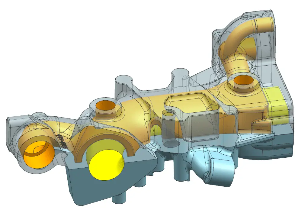
Exhaust Pipe
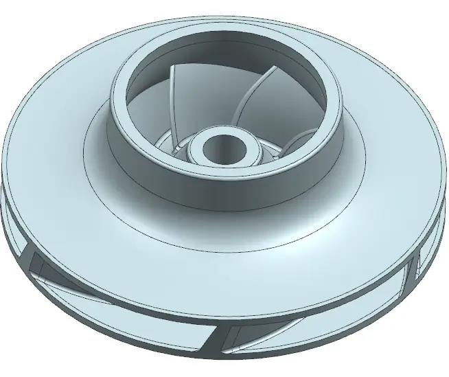
Impeller
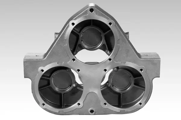
Typical Products
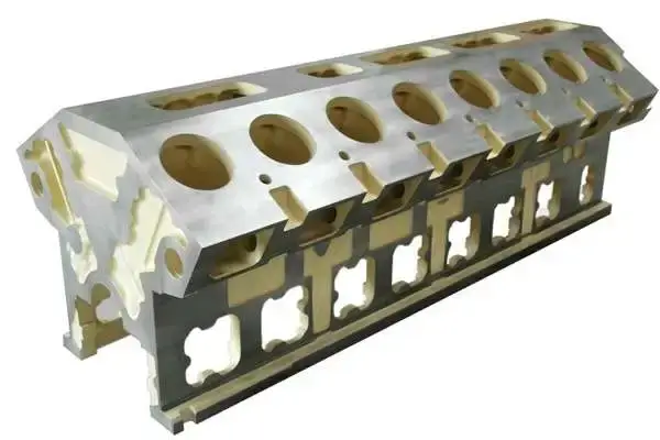
Cylinder Block
Material: Grey Iron
Application: High-horsepower Engine

Cylinder Head
Material: Ductile Iron
Application: High-horsepower Engine
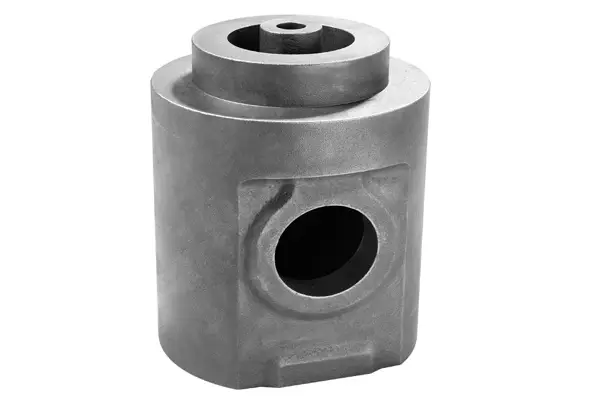
Cylinder Piston
Material: Ductile Iron
Application: High-horsepower Engine
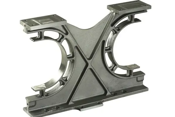
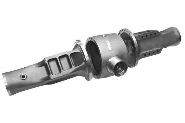
Frame
Material: Ductile Iron
Application: High-horsepower Locomotive Engine
Bracket
Material: Grey Iron
Application: High-horsepower Engine
![]()
Transmission System Impeller
Material:Ductile Iron
Application: Construction Equipment
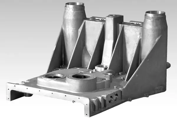
Housing
Material: Grey Iron
Application: High-horsepower Engine
Gearbox
Material: Grey Iron
Application:Construction Equipment
Axle
Material: Ductile Iron
Application: Agriculture Equipment

Torque Arm
Material: ADI Ductile Iron
Application: Wind Power Generation
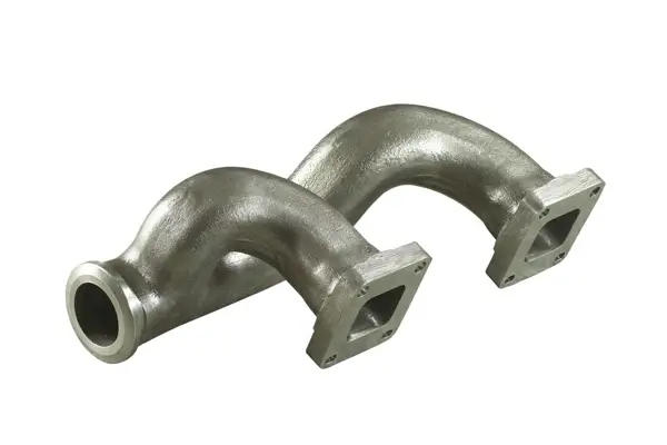
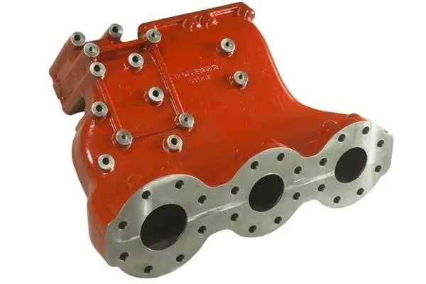
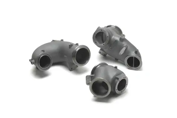
Manifold
Application: Construction Equipment and High-horsepower Engine
Combustor
Material:High Si-Mo ductile iron
Application: Construction Equipment and High-horsepower Engine